Tuesday, May 12, 2015

Conclusions

Hello Everyone,

I am sad to say we are about to wrap up our 2.00yoyo adventure. However, I am pleased to say, after an amazing semester with the best 2.008 team ever, we've produced 57 beautiful yoyos as shown in previous blog posts. To see our manufacture adventure video. Click here!


We were able to make a beautiful design without breaking our wallet. Below is our cost analysis of the compass yoyo manufacturing process.

Cost Estimates:


For the Yo-yo, we must estimate the cost per yoyo for a.) A 100 unit prototyping run and b.) A 100,000 unit per year manufacturing run should one day we decide to chase our dreams and make it all the way to S&P 500 with these yo-yos. As we learned in lecture, the cost of a manufacturing process can be summarized by 4 contributing aspects:

C1: The Material Cost, from the polystyrene for the injection mold to the acrylic for the compass needle, nothing is free, sadly.  This cost is calculated by multiplying the cost of the material per mass with the mass of materials needed for each part, over the ratio of materials that would actually be used to make the part as opposed to the scrap that comes with the part.
https://lh6.googleusercontent.com/oXLINF61Ya9qbbAQ_barzIIQf7--l6mCWGK9Pve1VnVRMK_2x-YDklgJ7FRNevGp1PTr6gul5LPrSW9FmdDF5L5vOQa-1n29ZGVFxUoge-suG9QGOFfnzfdcnG0T_SC9ibLFo8Q
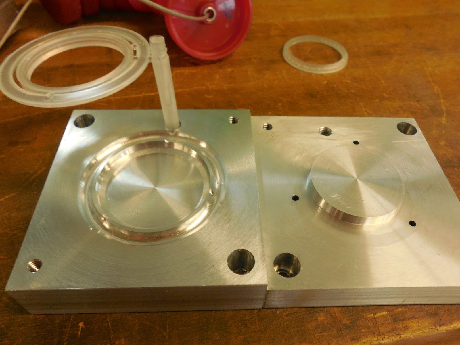
C2: The Cost of Tooling. In our case, this cost comes from the molds used for thermoforming and injection molding, and the cost to replace them after the molds have worn out. The cost is calculated by the cost of each tool over the number of units in a production run, multiplied by the closest integer of the units in a production run over the assumed number of units the tool can make before wearing out, plus 0.51.
https://lh5.googleusercontent.com/MmFjHwoeAUFPZumRhlXff0o_RJdbUNRixCW7DBqhCkqF4OiGDJa29sAcx4vxlaVZL3AnePMkXK41sPIBnObVnEM_SSxK7IV3J35LHTd_Rzz4TYPr4yH1G_72_EFBrA-igaAPt_w
C3: The Cost of Equipment. This covers the cost of buying the machines used during our production, such as the injection molding machine, thermoforming machine, and the laser cutter. (Thankfully, since we used the machines provided by school, they are 0 in real life!) The cost is calculated by the cost of the machine over its active life spam (projected life-spam time the ratio of when the machine will actually by running), all over the production rate of the run.
https://lh6.googleusercontent.com/Va4-IvO78wOKTel4G-uy7m2SI7_6NlgT8DwMoGmUJj_rab0Z4yiIMbaHgrA1uZ6VPJBGM6qQ_cq2abBvPt9KZaCgSm5cRLUchlX9_IUVQ7CrpNWF9z-MWMfsgQP0OlgBBfXKU9o
C4: The Cost of Overhead. This includes other forms of expenses, such as labor, energy, facilities, real-estate, etc. the calculation is simply the cost of overhead ($/time) over the production rate. For the overhead, we assumed just the labor cost, with a crew of 5, working at Massachusetts minimum wage ($9/hour), 45 hours a week, and for a year. We’ll sure find something on Craigslist.
Below is the projected cost per unit for both scenarios.
Type of Cost
Prototype Test Run
Manufacturing Run
Materials
$2.24/part
$2.24/part
Tooling
$0.8/part
$0.08/part
Equipment
$719.99/part
$0.719/part
Overhead
$1053/part
$1.053/part
Total
$1776.03/part
$3.1443/part


Reflection on Yo-Yo Design

While our vision of a compass yoyos was clear from day one, compromises had to be made to match the constraints of 2.008. One such compromise was the Thermoforming aspect. We had to make a design that would be compatible with the given punch and die set parameters.

Another constraint we faced was that due to the size constraints of the injection mold, we had to spread out the injection process into three molds, which equates to more tooling cost and time, which equates to more sadness. For mass manufacturing, we could acquire a machine that would allow a larger mold, so we could fit in more parts with each run, which means less tooling cost and time in the long run, which means more happiness.

Our biggest lesson we learned from the yoyo making lesson is that laser cutting may work for one yoyo. However, when we tried to use this process of multiple yoyos, the laser Acrylic sheet warped. This affect the quality of many of our yoyos. Some of the compass face broke as a resent of attempting to separate the compass face from the utensil. For compass faces that didn't break, the edges were not clean cut. This is one design aspect we would definitely redo for mas manufacturing; we could cut up the Acrylic sheet into appropriate sized squares prior to laser cutting, minimizing the affects of warping.

Future Recommendations

Learning Mastercam within a few weeks was quite a challenge. In fact, if it weren't from the guidance of the Daves, we wouldn't be where we are at today. One thing that helped us in particular was the Mastercam tutorial videos posted on the course locker, as they allow us to review the process we weren't clear of in our own time. The ability to pause and go back also helped us a lot, as we can't pause and rewind the Daves as freely as online video.

For the thermoform, we designed the initial process before knowing that there is a specific punch and die parameter. Perhaps a specification of all the available tools earlier in the lecture would be great.

The Labs are really constructive and fun, being able to experience with new tools and the manufacturing first hand. It is also great to see what we learned in lecture in action, and the Daves are always available to lend us their expertise. The only way to improve such great lab would be probably be to have a yoyo playing lesion, Dave style.

Friday, May 8, 2015

Yoyos yoyos and more yoyo!

Hi Everyone!

For the past few days, our yoyo team has been eating, sleeping, and breathing yoyos! As the semester is wrapping up, so is the yoyo project. Today, we just finished assembling all our yoyos and they look fabulous. We assembled 56 yoyos with one special limited Clare edition.

Assembled yoyos

Clare edition yoyo


Our yoyo is composed of
1. The (injection molded) body structure holding
2. The (laser cut) compass face on the needle pole
3. And the black (laser cut) needle.
4. The (injection molded)  cap keeps the needle on the pole. There is enough spacing between the cap and the needle to allow the needle to spin!
5. The compass face is held down by a (thermoformed) clear dome
7. And snap ring.
The colors were chosen accordingly to follow the steam-punk theme. When assembling the yoyo and keeping aesthetics in mind, the compass face north arrow were all chosen to align with the weld line. For functionality, the star design on the inner part of the yoyo body allows the string to wrap easily around the yoyo axle and do tricks.

Yoyo body with star design


While assembling, we faced some expected as well as unforeseen difficulties.
The expected difficulties come form the poorly manufactured parts (process change) to simulate malfunction in the manufacturing process. For example, some of the yoyo bodies were almost too small to hold the compass faces. This was due to the shortening of cooling time for the 10 defective yoyo bodies. In addition, some of the thermoformed dorms did not allow the snap ring to fit flush with the body. Due to a decrease in heating time for 10 of the thermoformed domes, the plastics' draw angles were too shallow for the snap ring to fit properly.

The unexpected manufacturing difficulty came in the laser cut compass face. We did not anticipate the acrylic to warp as a result of being overheated. This increased assembly time tremendously. Each compass face had to be painstakingly separated from the acrylic sheet. While doing this tedious task, some of the compass faces broke. Also, the edges on the non broken face were rough and not aesthetically pleasing. If were were to ever redo this assembly process, we will be cognizant of warping and the fragility of thin (1.8mm) acrylic cut out to fine designs.

Now that we are done with the yoyo adventure we decided to reflect and see how much things have changed from the original design. The major changes in design were very due to one mistake described in earlier blog posts (cutting the yoyo core too deep). Lucky for us, the mistake led to a redesign that eliminated an unneeded part (washer) and extra assembly time. Below is a more detailed assessment of how the final yoyo compares to our original design.

ItemDimensionDesign ValueDesign ToleranceActualReason
AssemblyMax Diameter2.464"± 0.003"2.510"The shrink rate was not as large as we expected. Therefore, the yoyo body is larger than our design. 
String Gap.15"± 0.005.15"On Target! 
Weight.15 lbs± 0.02 lbs.13 lbsOn Target
Compass FaceOuter Diameter2"± 0.005"2.005On Target
Thickness.0625"± 0.005".0625"On Target
Inner Hole Diameter.25"+ 0.005"0.495"This was made larger to fit over the redesigned compass needle pole. 


Extrusion Pole for NeedleOuter Diameter0.23"0.005"0.490"The pole was made larger as a result of the core accidentally being machined too deep. Instead of re-machining the yoyo body to fit with our old washer design, we decided to change the compass pole.diameter 
Inner Diameter0.20"0.005"0.23"The pole was made larger as a result of the core accidentally being machined too deep. Instead of re-machining the yoyo body to fit with our old washer design, we decided to change the compass pole diameter.
Height0.22"0.005"0.35"This change was due to cutting the core mold too deep
Thermoform CapCap Outer Diameter1.76"+ 0.005"1.813"The draw angle is not as sharp as an ideal CAD drawing. Therefore, the actual outer diameter is slightly larger than the CAD designed outer diameter 
Yoyo BodyCavity Diameter2"- 0.005"2.014"The shrink rate was not as large as we expected. Therefore, the yoyo body is larger than our design. 
Snap RingOuter Diameter2.040"+ 0.005"2.035"On Target!
Inner Diameter1.845"+ 0.005""1.829"The shrink rate for the snap ring was larger than expected. 

Before assembling, we graphed run charts and xbar charts for critical dimensions. These charts and findings are discussed in more detail in lab deliverable 4. Continuing with the yoyo body Odyssey, we decided the inner cavity diameter was the critical feature due to the fact that the snap ring, dome, and compass face all had to fit flush within (we don't want the yoyo to fall apart!). Fortunately, the yoyo body did not show much variation (no process change could be detected) and stayed within in a range of 0.005". The Cp calculated for the yoyo body was 0.4289 indicating some yoyos fell outside our upper limit and lower limit range. If a yoyo was out of USL and LSL range, it was usually below specifications. This makes sense as the process change was a shorting cooling time leading to a shrunken yoyo. However, despite some variation, we still had enough bodies to make at least 50 yoyos.

Our team had fun assembling the 60 yoyos.

We will end the blog post on a happy note! Team boding! (thank you James for providing us with macaroons to get through this tedious task!)
Note: Photographer Clare Zhang not pictured.
"My little yoyo"

"Look at our yoyo!"

Quality inspection

MTTR. Repairing poorly manufactured yoyos

"We minimized our buffers! Now we have a good assembly line"

So much fun!

Team Bonding. Not pictured: Photographer Clare

"Don't bother me, I'm working"

"Almost, Almost" 

"Look! I learned how to yoyo!"

"OMG yoyos!" 

Tedious laser cut cleaning


Please stay tuned for next week. We have a fun surprise!

Monday, April 27, 2015

Optimization

The adventure continues with 2.00yoyo. Last time, we talked about the Odyssey with the Yoyo body part. Now that we resolved the almost disaster, we were able to start optimizing injection molding parameters.
Below are the injection molding parameters decided for yoyo body.

Injection Molding Parameters

Part: Body Mold

Injection Mold

Injection Mold Pressure Profile: P7-P16
600
700
800
800
800
700
650
650
600
500
Injection Hold Time
Z2= 8 Seconds
Cooling Time
Z4= 20 Seconds
Set Screw Feed Stroke
C1= 2.75”

Injection Boost

Injection Speed Profile: V12-V21
1.5
2.0
2.5
3.0
2.0
1.5
1.0
0.7
0.5
0.2
Injection Boost Pressure
P6= 1400 psi

Screw Feeding

Screw Feed Delay time
Z3= 20 Seconds

Ejector

Ejector Counter
AZ= 2

Ejector Pin Length: 5.647”

Total Shim Thickness:


These parameters were chosen to produce the best looking yoyo body. The pressure of 1400psi was optimized to prevent flash. The cooling time of 20s prevents the yoyo body from over shrinking and warping. 
At first, the snap ring did not fit into the yoyo body snugly. This was due to difference in shrinkage rates between the yoyo body and snap ring. To compensate for the differences, the Yoyo body cooling time was 5s more than the cooling time for the yoyo snap ring. This way the snap ring shrinks less than the yoyo body, allowing tighter tolerances and fit between the yoyo body and the snap ring. The ejector pin lengths were chosen to only protrude when the springs compress to eject the yoyo body.

Besides the design change explained in last week's blog, no real design change has been made thus far.
We were able to do optimization runs for all our parts (thermoforming snap ring, laser cutting compass face/needle, and injection molding the yoyo body, camp and snap ring). 
The only difficulty we faced in the optimization process was for the thermoformed part. At first, the plastic did not draw towards the mold. We initially thought this was due to lack of proper air pressure. However, we decided to raise the oven temperature (from 650F to 675F) and increase heating time to make the plastic more soft and easy to draw. This fixed our problems and allowed the snap ring to fit comfortably over the thermoform dome.
Our preliminary yoyo looks like this.

Dave was able to practice some tricks with the yoyo. The yoyo needle is able to spin when in use! 
After the optimization run, production runs were done for the snap ring, yoyo body, and the needle cap. Production runs to be done are the thermoformed dome and the laser cut compass face/needle. 

Lucky for us, this week, work went smoothly and we already conquered the biggest design change (explained in last week's blog), we were able to work productively as a team! 

Below are pictures of our team bonding and working! 

Connor testing out our new yoyo! 

Production run of snap ring

Connor and Kate meticulously keeping track of snap rings quality 

Beckett preparing the needle pins for the yoyo body

Production run of the Yoyo bodies

Team work!!!!!! (Production run of the yoyo body) 


Sunday, April 5, 2015

Mens et manus: From Ideas to Tangible Creations


Hello World! In the past few weeks our team has been preparing the yoyo molds. After much brainstorming, we were able to start writing Mastercam code and process plans. Below is our ambitious estimate for manufacture time. 
Manufacturing Time
Thermoform Mold Machining (Lathe) Time
Front: 1m3.34s
Back: 14.58s
Time~(thickness)^2/alpha
~0.000762^2/(0.096*10^-6)
~6.048seconds
Lathe Machining Time for Body Mold:
Lathe Cavity of Body Mold: 10m30.57s
Lathe Core of Body Mold: 10m25.58s
Mill Machining Time for Body Mold:
Mill Cavity of Body Mold: 47.19s
Mill Core of Body Mold: 3m38.22s
Body Mold time:
Time~ (thickness)^2/alpha
      ~(0.014224^2)/(0.096*10^-6)
      ~35mins.
Snap Ring Time:
Lathe Cavity: 1min
Lathe Core: 1min
Mill Cavity: 4min
Mill Core: 1min
Time ~ (thickness)^2/alpha
     ~ (.003m)^2/(0.096 × 10−6)
 Cooling ~order of 1.5min, let’s say 5min


TOTAL TIME: 12 min
Cap Mold
Cavity: 8m32.61s
Core: 15m15.16s
Time~ (Thickness)^2/alpha
~(0.00255016^2)/(0.096*10^-6)
~1.13 mins, let’s say 5 mins
Washer Mold
Cavity:8m46..41s
Core:17m19.91s
Time ~(Thickness)^2/alpha
~(0.006477^2)/(0.096*10^-6)
~7.28 mins, let’s go with 15 mins
Laser Cutting:
Estimate ~5 minutes for compass and needle
For the machines, we assumed the lathe time is accurate, and the core time may have up to a two minute delay for each tool change. For laser cutting, we assume to make 10 parts per operation, which will take around 5 minutes each. For the cooling, we assumed cooling time can be derived using the thickest part of the mold, and insert into the function ((Thickness)^2)/(0.096*10^-6) to derive the time. 
All our manufacturing process planning (Please click here to see detailed process plan) was finished prior to spring break. We had to wait an agonizing week to start machining!

Over spring break, some of us could not stay away from the excitement of 2.00yoyo and started machining the molds. The molds were finished as of Friday 4/3. We even started making some injection molded parts! 

Below are some pictures of our molds. 
Yoyo Cap Mold 

Yoyo Body Mold
Yoyo Thermoforming Mold
Yoyo Snap Ring Mold
We tested some of the snap ring and yoyo body parts. Below are pictures of success and failures. The failure was do to short-shot, the injection pressures and temperature was not high enough to push the melted plastic throughout the mold. 
Successful Yoyo Body with Snap Ring! 
Yoyo Snap Ring
Unsuccessful Short Shot Yoyo body :(
After an initial short shot yoyo body test, we adjusted the amount of plastic ejected into our mold.  Our next two tests were much more successful, and we were able to create our very first yoyo (minus the bells and whistles) shown above.

As typical in building processes, not everything goes smoothly or always according to plan.  Due to some miscalculations, our original Yoyo design underwent urgent revival. Here begins the odyssey of the Yoyo body. 
Below is the design of our original Yoyo body. 

This design included the following parts
1. Yoyo Body 
2. Compass Face and Needle (for aesthetic purposes)
3. Thermoform Cover
4. Cap (to hold down compass needle) 
5. Snap Ring (To hold down compass face and thermoform cover)
6. Dowel rods for Yoyo Axle 
7. Washer (To allow the compass needle to spin) 

When transferring the Solidworks files to the Mastercam files, we were cognizant of shrinkage. We took shrinkage rates from previous injection molded parts of the same volume and applied those to calculating the needed mold size. In our case we used a 2% shrinkage rate. 

After what we created what we thought were flawless G-codes, we went on to machining. A few simple mistakes were made. Tool 17 was not preset to have a pecking motion. As a result the tool got damaged and the ejector pin holes didn't go all the way through. But that mistake was easily fixed with a drill press. When we finished all our molds, we had a new sinking revelation: the yoyo body cavity was cut too deep! "There goes hours of our machine work!" we lamented. 

However, Kate, with her positive attitude (and desire to optimize lab time) came to save the day! "We can change our Yoyo design! No need to remachine everything!" Instead of creating a new cavity mold (time is precious and we cannot waste it if we hope to make 50 yoyos by May), we faced the rest of the core mold to have the same offset as the miscalculations. This change worked with all our existing parts except the washer. Luckily, the washer was the only mold we did not make yet. Perhaps this mistake was not a coincidence or a mistake. After all, it spared us have making another mold, and having to manage another part in our assembly. Our new manufacturing time should now be shorter by at least 3 hours (1 for manufacturing the body mold, 1 for optimizing injection molding parameters, 1 injection molding 50 washers, not to mention assembly time that accumulates). Below is a revised list of our yoyo parts: 
1. Yoyo Body
2. Compass Face and Needle (for aesthetic purposes)
3. Thermoform Cover
4. Cap (to hold down compass needle) 
5. Snap Ring (To hold down compass face and thermoform cover)
6. Dowel rods for Yoyo Axle 

Below is a Solidworks model of our revised design. 
The Revised Yoyo does not have a washer. The compass face inner diameter must also be made larger to fit in the yoyo. 
The best part of the odyssey was the team alliance formed and reaffirmed. After struggling through this ordeal and redesign, we managed to still tolerate each other and dare I say call each other friends!? Team 2.00yoyo still remains strong. Stay tuned for next week!

Below are some fun pictures of our team hard at work. SPECIAL THANKS TO DAVE AND DAVE for guiding ups through the machining and Mastercaming.
Connor intent on making sure the milling is executed perfectly

Kate and Beckett listening carefully to wise Dave

Clare focusing on her snap ring mold
Kate and Beckett Showing off their wonderful creation 
Clare Demonstrating our functional Yoyo!
James and Emma working on the cap core mold