Hello World! In the past few weeks our team has been preparing the yoyo molds. After much brainstorming, we were able to start writing Mastercam code and process plans. Below is our ambitious estimate for manufacture time.
Manufacturing Time
For the machines, we assumed the lathe time is accurate, and the core time may have up to a two minute delay for each tool change. For laser cutting, we assume to make 10 parts per operation, which will take around 5 minutes each. For the cooling, we assumed cooling time can be derived using the thickest part of the mold, and insert into the function ((Thickness)^2)/(0.096*10^-6) to derive the time.
Thermoform Mold Machining (Lathe) Time
|
Front: 1m3.34s
Back: 14.58s Time~(thickness)^2/alpha ~0.000762^2/(0.096*10^-6) ~6.048seconds |
Lathe Machining Time for Body Mold:
|
Lathe Cavity of Body Mold: 10m30.57s
Lathe Core of Body Mold: 10m25.58s
|
Mill Machining Time for Body Mold:
|
Mill Cavity of Body Mold: 47.19s
Mill Core of Body Mold: 3m38.22s
|
Body Mold time:
|
Time~ (thickness)^2/alpha
~(0.014224^2)/(0.096*10^-6) ~35mins. |
Snap Ring Time:
|
Lathe Cavity: 1min
Lathe Core: 1min
Mill Cavity: 4min
Mill Core: 1min
Time ~ (thickness)^2/alpha
~ (.003m)^2/(0.096 × 10−6)
Cooling ~order of 1.5min, let’s say 5min
TOTAL TIME: 12 min
|
Cap Mold
|
Cavity: 8m32.61s
Core: 15m15.16s
Time~ (Thickness)^2/alpha ~(0.00255016^2)/(0.096*10^-6)
~1.13 mins, let’s say 5 mins
|
Washer Mold
|
Cavity:8m46..41s
Core:17m19.91s Time ~(Thickness)^2/alpha ~(0.006477^2)/(0.096*10^-6)
~7.28 mins, let’s go with 15 mins
|
Laser Cutting:
|
Estimate ~5 minutes for compass and needle
|
All our manufacturing process planning (Please click here to see detailed process plan) was finished prior to spring break. We had to wait an agonizing week to start machining!
Over spring break, some of us could not stay away from the excitement of 2.00yoyo and started machining the molds. The molds were finished as of Friday 4/3. We even started making some injection molded parts!
Below are some pictures of our molds.
 |
| Yoyo Cap Mold |
 |
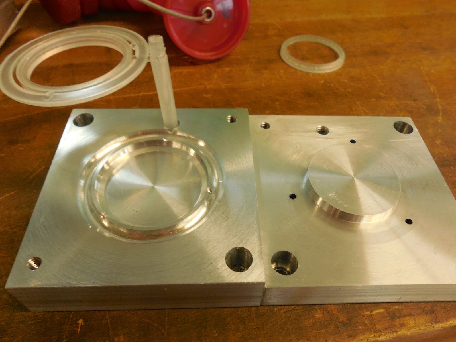
| Yoyo Body Mold |
 |
| Yoyo Thermoforming Mold |
 |
| Yoyo Snap Ring Mold
We tested some of the snap ring and yoyo body parts. Below are pictures of success and failures. The failure was do to short-shot, the injection pressures and temperature was not high enough to push the melted plastic throughout the mold.
|
 |
| Successful Yoyo Body with Snap Ring! |
 |
| Yoyo Snap Ring |
 |
| Unsuccessful Short Shot Yoyo body :( |
As typical in building processes, not everything goes smoothly or always according to plan. Due to some miscalculations, our original Yoyo design underwent urgent revival. Here begins the odyssey of the Yoyo body.
Below is the design of our original Yoyo body.

This design included the following parts
1. Yoyo Body
2. Compass Face and Needle (for aesthetic purposes)
3. Thermoform Cover
4. Cap (to hold down compass needle)
5. Snap Ring (To hold down compass face and thermoform cover)
6. Dowel rods for Yoyo Axle
7. Washer (To allow the compass needle to spin)
When transferring the Solidworks files to the Mastercam files, we were cognizant of shrinkage. We took shrinkage rates from previous injection molded parts of the same volume and applied those to calculating the needed mold size. In our case we used a 2% shrinkage rate.
After what we created what we thought were flawless G-codes, we went on to machining. A few simple mistakes were made. Tool 17 was not preset to have a pecking motion. As a result the tool got damaged and the ejector pin holes didn't go all the way through. But that mistake was easily fixed with a drill press. When we finished all our molds, we had a new sinking revelation: the yoyo body cavity was cut too deep! "There goes hours of our machine work!" we lamented.
However, Kate, with her positive attitude (and desire to optimize lab time) came to save the day! "We can change our Yoyo design! No need to remachine everything!" Instead of creating a new cavity mold (time is precious and we cannot waste it if we hope to make 50 yoyos by May), we faced the rest of the core mold to have the same offset as the miscalculations. This change worked with all our existing parts except the washer. Luckily, the washer was the only mold we did not make yet. Perhaps this mistake was not a coincidence or a mistake. After all, it spared us have making another mold, and having to manage another part in our assembly. Our new manufacturing time should now be shorter by at least 3 hours (1 for manufacturing the body mold, 1 for optimizing injection molding parameters, 1 injection molding 50 washers, not to mention assembly time that accumulates). Below is a revised list of our yoyo parts:
1. Yoyo Body
2. Compass Face and Needle (for aesthetic purposes)
3. Thermoform Cover
4. Cap (to hold down compass needle)
5. Snap Ring (To hold down compass face and thermoform cover)
6. Dowel rods for Yoyo Axle
Below is a Solidworks model of our revised design.
 |
| The Revised Yoyo does not have a washer. The compass face inner diameter must also be made larger to fit in the yoyo. |
Below are some fun pictures of our team hard at work. SPECIAL THANKS TO DAVE AND DAVE for guiding ups through the machining and Mastercaming.
 |
| Connor intent on making sure the milling is executed perfectly |
 |
| Kate and Beckett listening carefully to wise Dave |
 |
| Clare focusing on her snap ring mold |
 |
| Kate and Beckett Showing off their wonderful creation |

Clare Demonstrating our functional Yoyo!
James and Emma working on the cap core mold
No comments:
Post a Comment